
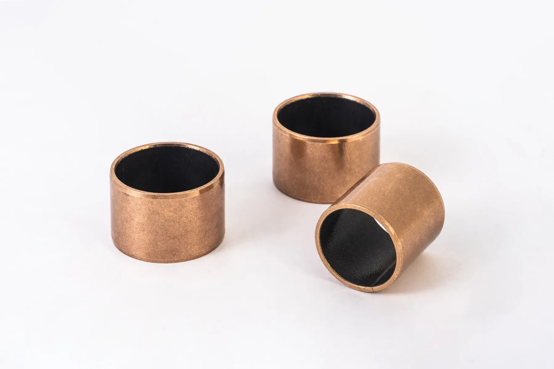
Bronze bushing sizes
The standard metric bronze bushing series is ISO 4379 (formerly DIN 1850): cylindrical sleeves and flanged bushings from Ø6 to Ø200 mm bore, each bore in three wall thicknesses and two or three lengths. The tables below give every size in the standard with its tolerances; anything else, including inch sizes, is machined to your drawing in the same alloys.
A bronze bushing size is written bore × outside diameter × length: 40 × 48 × 40 is a 40 mm bore, 48 mm outside diameter (4 mm wall) and 40 mm long. The nominal size fixes the envelope; the tolerance class fixes how the bushing fits the housing and the shaft, and ISO 4379 defines both.
- Cylindrical sleeves (Type C) and flanged bushings (Type F), Ø6–200 mm bore, 46 bores each
- Three outside diameters per bore: thin, medium and thick wall; lengths from 6 to 250 mm
- Bore E6 before fitting, outside diameter s6 / r6, flange d11, length h13
- Standard alloy C93200 / SAE 660; C90500, C95400, C86300 and sintered bronze on request
- Machining range Ø3–1000 mm; inch sizes and non-standard walls to drawing, no minimum order
Cylindrical bronze sleeve bushings, ISO 4379 Type C (mm)
Standard metric series. Each bore is offered in three outside diameters (thin, medium and thick wall) and the lengths listed. Sizes in parentheses are marked “for special applications only” in the standard.
| Bore d | Outside Ø D (thin) | Ø D (medium) | Ø D (thick) | Lengths L | Wall | Chamfer 45° max | Quote |
|---|---|---|---|---|---|---|---|
| Ø6 sleeve | 8 | 10 | 12 | 6 · 10 | 1–3 | 0.3 | Quote |
| Ø8 sleeve | 10 | 12 | 14 | 6 · 10 | 1–3 | 0.3 | Quote |
| Ø10 sleeve | 12 | 14 | 16 | 6 · 10 | 1–3 | 0.3 | Quote |
| Ø12 sleeve | 14 | 16 | 18 | 10 · 15 · 20 | 1–3 | 0.5 | Quote |
| Ø14 sleeve | 16 | 18 | 20 | 10 · 15 · 20 | 1–3 | 0.5 | Quote |
| Ø15 sleeve | 17 | 19 | 21 | 10 · 15 · 20 | 1–3 | 0.5 | Quote |
| Ø16 sleeve | 18 | 20 | 22 | 12 · 15 · 20 | 1–3 | 0.5 | Quote |
| Ø18 sleeve | 20 | 22 | 24 | 12 · 20 · 30 | 1–3 | 0.5 | Quote |
| Ø20 sleeve | 23 | 24 | 26 | 15 · 20 · 30 | 1.5–3 | 0.5 | Quote |
| Ø22 sleeve | 25 | 26 | 28 | 15 · 20 · 30 | 1.5–3 | 0.5 | Quote |
| (Ø24 sleeve) | 27 | 28 | 30 | 15 · 20 · 30 | 1.5–3 | 0.5 | Quote |
| Ø25 sleeve | 28 | 30 | 32 | 20 · 30 · 40 | 1.5–3.5 | 0.5 | Quote |
| (Ø27 sleeve) | 30 | 32 | 34 | 20 · 30 · 40 | 1.5–3.5 | 0.5 | Quote |
| Ø28 sleeve | 32 | 34 | 36 | 20 · 30 · 40 | 2–4 | 0.5 | Quote |
| Ø30 sleeve | 34 | 36 | 38 | 20 · 30 · 40 | 2–4 | 0.5 | Quote |
| Ø32 sleeve | 36 | 38 | 40 | 20 · 30 · 40 | 2–4 | 0.8 | Quote |
| (Ø33 sleeve) | 37 | 40 | 42 | 20 · 30 · 40 | 2–4.5 | 0.8 | Quote |
| Ø35 sleeve | 39 | 41 | 45 | 30 · 40 · 50 | 2–5 | 0.8 | Quote |
| (Ø36 sleeve) | 40 | 42 | 46 | 30 · 40 · 50 | 2–5 | 0.8 | Quote |
| Ø38 sleeve | 42 | 45 | 48 | 30 · 40 · 50 | 2–5 | 0.8 | Quote |
| Ø40 sleeve | 44 | 48 | 50 | 30 · 40 · 60 | 2–5 | 0.8 | Quote |
| Ø42 sleeve | 46 | 50 | 52 | 30 · 40 · 60 | 2–5 | 0.8 | Quote |
| Ø45 sleeve | 50 | 53 | 55 | 30 · 40 · 60 | 2.5–5 | 0.8 | Quote |
| Ø48 sleeve | 53 | 56 | 58 | 40 · 50 · 60 | 2.5–5 | 0.8 | Quote |
| Ø50 sleeve | 55 | 58 | 60 | 40 · 50 · 60 | 2.5–5 | 0.8 | Quote |
| Ø55 sleeve | 60 | 63 | 65 | 40 · 50 · 70 | 2.5–5 | 0.8 | Quote |
| Ø60 sleeve | 65 | 70 | 75 | 40 · 60 · 80 | 2.5–7.5 | 0.8 | Quote |
| Ø65 sleeve | 70 | 75 | 80 | 50 · 60 · 80 | 2.5–7.5 | 1 | Quote |
| Ø70 sleeve | 75 | 80 | 85 | 50 · 70 · 90 | 2.5–7.5 | 1 | Quote |
| Ø75 sleeve | 80 | 85 | 90 | 50 · 70 · 90 | 2.5–7.5 | 1 | Quote |
| Ø80 sleeve | 85 | 90 | 95 | 60 · 80 · 100 | 2.5–7.5 | 1 | Quote |
| Ø85 sleeve | 90 | 95 | 100 | 60 · 80 · 100 | 2.5–7.5 | 1 | Quote |
| Ø90 sleeve | 100 | 105 | 110 | 60 · 80 · 120 | 5–10 | 1 | Quote |
| Ø95 sleeve | 105 | 110 | 115 | 60 · 100 · 120 | 5–10 | 1 | Quote |
| Ø100 sleeve | 110 | 115 | 120 | 80 · 100 · 120 | 5–10 | 1 | Quote |
| Ø105 sleeve | 115 | 120 | 125 | 80 · 100 · 120 | 5–10 | 1 | Quote |
| Ø110 sleeve | 120 | 125 | 130 | 80 · 100 · 120 | 5–10 | 1 | Quote |
| Ø120 sleeve | 130 | 135 | 140 | 100 · 120 · 150 | 5–10 | 1 | Quote |
| Ø130 sleeve | 140 | 145 | 150 | 100 · 120 · 150 | 5–10 | 2 | Quote |
| Ø140 sleeve | 150 | 155 | 160 | 100 · 150 · 180 | 5–10 | 2 | Quote |
| Ø150 sleeve | 160 | 165 | 170 | 120 · 150 · 180 | 5–10 | 2 | Quote |
| Ø160 sleeve | 170 | 180 | 185 | 120 · 150 · 180 | 5–12.5 | 2 | Quote |
| Ø170 sleeve | 180 | 190 | 195 | 120 · 180 · 200 | 5–12.5 | 2 | Quote |
| Ø180 sleeve | 190 | 200 | 210 | 150 · 180 · 250 | 5–15 | 2 | Quote |
| Ø190 sleeve | 200 | 210 | 220 | 150 · 180 · 250 | 5–15 | 2 | Quote |
| Ø200 sleeve | 210 | 220 | 230 | 180 · 200 · 250 | 5–15 | 2 | Quote |
Type a bore in the filter box to find a size. Every row is machined to order in C93200 / SAE 660 unless another alloy is specified; sizes between the rows are quoted from the drawing.
Flanged bronze bushings, ISO 4379 Type F (mm)
Series 1 has a thin flange (thickness t 1–5 mm), Series 2 a heavy flange (3–15 mm). Lengths L include the flange.
| Bore d | Series 1 D × F × t | Series 2 D × F × t | Lengths L | Undercut u | Chamfer 45° max | Quote |
|---|---|---|---|---|---|---|
| Ø6 flanged | 8 × 10 × 1 | 12 × 14 × 3 | 6 · 10 | 1 | 0.3 | Quote |
| Ø8 flanged | 10 × 12 × 1 | 14 × 18 × 3 | 6 · 10 | 1 | 0.3 | Quote |
| Ø10 flanged | 12 × 14 × 1 | 16 × 20 × 3 | 6 · 10 | 1 | 0.3 | Quote |
| Ø12 flanged | 14 × 16 × 1 | 18 × 22 × 3 | 10 · 15 · 20 | 1 | 0.5 | Quote |
| Ø14 flanged | 16 × 18 × 1 | 20 × 25 × 3 | 10 · 15 · 20 | 1 | 0.5 | Quote |
| Ø15 flanged | 17 × 19 × 1 | 21 × 27 × 3 | 10 · 15 · 20 | 1 | 0.5 | Quote |
| Ø16 flanged | 18 × 20 × 1 | 22 × 28 × 3 | 12 · 15 · 20 | 1.5 | 0.5 | Quote |
| Ø18 flanged | 20 × 22 × 1 | 24 × 30 × 3 | 12 · 20 · 30 | 1.5 | 0.5 | Quote |
| Ø20 flanged | 23 × 26 × 1.5 | 26 × 32 × 3 | 15 · 20 · 30 | 1.5 | 0.5 | Quote |
| Ø22 flanged | 25 × 28 × 1.5 | 28 × 34 × 3 | 15 · 20 · 30 | 1.5 | 0.5 | Quote |
| (Ø24 flanged) | 27 × 30 × 1.5 | 30 × 36 × 3 | 15 · 20 · 30 | 1.5 | 0.5 | Quote |
| Ø25 flanged | 28 × 31 × 1.5 | 32 × 38 × 4 | 20 · 30 · 40 | 1.5 | 0.5 | Quote |
| (Ø27 flanged) | 30 × 33 × 1.5 | 34 × 40 × 4 | 20 · 30 · 40 | 1.5 | 0.5 | Quote |
| Ø28 flanged | 32 × 36 × 2 | 36 × 42 × 4 | 20 · 30 · 40 | 1.5 | 0.5 | Quote |
| Ø30 flanged | 34 × 38 × 2 | 38 × 44 × 4 | 20 · 30 · 40 | 2 | 0.5 | Quote |
| Ø32 flanged | 36 × 40 × 2 | 40 × 46 × 4 | 20 · 30 · 40 | 2 | 0.8 | Quote |
| (Ø33 flanged) | 37 × 41 × 2 | 42 × 48 × 5 | 20 · 30 · 40 | 2 | 0.8 | Quote |
| Ø35 flanged | 39 × 43 × 2 | 45 × 50 × 5 | 30 · 40 · 50 | 2 | 0.8 | Quote |
| (Ø36 flanged) | 40 × 44 × 2 | 46 × 52 × 5 | 30 · 40 · 50 | 2 | 0.8 | Quote |
| Ø38 flanged | 42 × 46 × 2 | 48 × 54 × 5 | 30 · 40 · 50 | 2 | 0.8 | Quote |
| Ø40 flanged | 44 × 48 × 2 | 50 × 58 × 5 | 30 · 40 · 60 | 2 | 0.8 | Quote |
| Ø42 flanged | 46 × 50 × 2 | 52 × 60 × 5 | 30 · 40 · 60 | 2 | 0.8 | Quote |
| Ø45 flanged | 50 × 55 × 2.5 | 55 × 63 × 5 | 30 · 40 · 60 | 2 | 0.8 | Quote |
| Ø48 flanged | 53 × 58 × 2.5 | 58 × 66 × 5 | 40 · 50 · 60 | 2 | 0.8 | Quote |
| Ø50 flanged | 55 × 60 × 2.5 | 60 × 68 × 5 | 40 · 50 · 60 | 2 | 0.8 | Quote |
| Ø55 flanged | 60 × 65 × 2.5 | 65 × 73 × 5 | 40 · 50 · 70 | 2 | 0.8 | Quote |
| Ø60 flanged | 65 × 70 × 2.5 | 75 × 83 × 7.5 | 40 · 60 · 80 | 2 | 0.8 | Quote |
| Ø65 flanged | 70 × 75 × 2.5 | 80 × 88 × 7.5 | 50 · 60 · 80 | 2 | 1 | Quote |
| Ø70 flanged | 75 × 80 × 2.5 | 85 × 95 × 7.5 | 50 · 70 · 90 | 2 | 1 | Quote |
| Ø75 flanged | 80 × 85 × 2.5 | 90 × 100 × 7.5 | 50 · 70 · 90 | 3 | 1 | Quote |
| Ø80 flanged | 85 × 90 × 2.5 | 95 × 105 × 7.5 | 60 · 80 · 100 | 3 | 1 | Quote |
| Ø85 flanged | 90 × 95 × 2.5 | 100 × 110 × 7.5 | 60 · 80 · 100 | 3 | 1 | Quote |
| Ø90 flanged | 100 × 110 × 5 | 110 × 120 × 10 | 60 · 80 · 120 | 3 | 1 | Quote |
| Ø95 flanged | 105 × 115 × 5 | 115 × 125 × 10 | 60 · 100 · 120 | 3 | 1 | Quote |
| Ø100 flanged | 110 × 120 × 5 | 120 × 130 × 10 | 80 · 100 · 120 | 3 | 1 | Quote |
| Ø105 flanged | 115 × 125 × 5 | 125 × 135 × 10 | 80 · 100 · 120 | 3 | 1 | Quote |
| Ø110 flanged | 120 × 130 × 5 | 130 × 140 × 10 | 80 · 100 · 120 | 3 | 1 | Quote |
| Ø120 flanged | 130 × 140 × 5 | 140 × 150 × 10 | 100 · 120 · 150 | 3 | 1 | Quote |
| Ø130 flanged | 140 × 150 × 5 | 150 × 160 × 10 | 100 · 120 · 150 | 4 | 2 | Quote |
| Ø140 flanged | 150 × 160 × 5 | 160 × 170 × 10 | 100 · 150 · 180 | 4 | 2 | Quote |
| Ø150 flanged | 160 × 170 × 5 | 170 × 180 × 10 | 120 · 150 · 180 | 4 | 2 | Quote |
| Ø160 flanged | 170 × 180 × 5 | 185 × 200 × 12.5 | 120 · 150 · 180 | 4 | 2 | Quote |
| Ø170 flanged | 180 × 190 × 5 | 195 × 210 × 12.5 | 120 · 180 · 200 | 4 | 2 | Quote |
| Ø180 flanged | 190 × 200 × 5 | 210 × 220 × 15 | 150 · 180 · 250 | 4 | 2 | Quote |
| Ø190 flanged | 200 × 210 × 5 | 220 × 230 × 15 | 150 · 180 · 250 | 4 | 2 | Quote |
| Ø200 flanged | 210 × 220 × 5 | 230 × 240 × 15 | 180 · 200 · 250 | 4 | 2 | Quote |
D = outside diameter, F = flange diameter, t = flange thickness. Flange diameter tolerance d11; the flange face can be drilled for a locating screw or pin on request.
Tolerances and resulting fits (µm)
ISO 4379 Table 3. The bore is finished E6 before fitting and closes to about H8 when the bushing is pressed into an H7 housing; the outside diameter is s6 (to Ø120) or r6 (over Ø120). Fits are computed from the ISO 286-2 deviations.
| Nominal size over–to | Bore E6 | Outside s6 / r6 | Housing H7 | Shaft e7 | Interference OD in H7 | Running clearance vs e7 |
|---|---|---|---|---|---|---|
| 6–10 | +34 / +25 | +32 / +23 | +15 / +0 | -25 / -40 | 8–32 | 25–62 |
| 10–18 | +43 / +32 | +39 / +28 | +18 / +0 | -32 / -50 | 10–39 | 32–77 |
| 18–30 | +53 / +40 | +48 / +35 | +21 / +0 | -40 / -61 | 14–48 | 40–94 |
| 30–50 | +66 / +50 | +59 / +43 | +25 / +0 | -50 / -75 | 18–59 | 50–114 |
| 50–80 | +79 / +60 | +78 / +59 | +30 / +0 | -60 / -90 | 29–78 | 60–136 |
| 80–120 | +94 / +72 | +101 / +79 | +35 / +0 | -72 / -107 | 44–101 | 72–161 |
| 120–180 | +110 / +85 | +93 / +68 | +40 / +0 | -85 / -125 | 28–93 | 85–188 |
| 180–250 | +129 / +100 | +113 / +84 | +46 / +0 | -100 / -146 | 38–113 | 100–218 |
Deviations in micrometres (upper / lower). The interference and clearance columns are the min–max of the pairing; a thin-wall sleeve closes more on pressing than a thick one, so check the fitted bore on the first-off part.
How to read the tables
ISO 4379 lists one bore per row and three outside diameters for it. The thin-wall diameter is for housings with little room or where the bushing is a wear liner in a stiff bore; the medium and thick walls carry heavier loads, tolerate a housing that is not perfectly round and leave stock for re-machining the bore after pressing. The lengths are the standard cuts; a sleeve can be supplied in any length up to the longest listed without a tooling change.
Flanged bushings come in two flange series. Series 1 (thin flange) locates the bushing axially and takes only light thrust; Series 2 (heavy flange) is for thrust loads and for housings where the flange is drilled and pinned. The length L includes the flange thickness t.
Sizes in parentheses are in the standard but flagged as “to be avoided”: they exist for legacy designs and are quoted like any other size.
Fits: interference in the housing, clearance on the shaft
The outside diameter is finished s6 up to Ø120 mm and r6 above, which gives a firm press fit in an H7 housing: for a Ø40 bushing the interference is 18–59 µm. Pressing closes the bore by roughly the same amount, so ISO 4379 has the bore finished E6 before fitting and expects about H8 after fitting. Against a general-duty e7 shaft the running clearance at Ø40 is then 50–114 µm, which is the normal range for a grease- or oil-lubricated bronze bushing at moderate speed.
If the application needs a tighter or wider clearance (precision g7 shafts, dirty grease, thermal growth of an aluminium housing), specify the shaft tolerance on the enquiry and we finish the bore to suit. For bushings that are line-bored after pressing, order the bore with machining stock instead.
| Size | Interference in H7 housing | Clearance vs e7 shaft | Note |
|---|---|---|---|
| 20 × 24 × 20 | 14–48 µm | 40–94 µm | Light machinery pivot |
| 40 × 48 × 40 | 18–59 µm | 50–114 µm | General duty |
| 60 × 70 × 60 | 29–78 µm | 60–136 µm | Agricultural, hydraulic cylinder eyes |
| 100 × 115 × 100 | 44–101 µm | 72–161 µm | Slow, heavy load; check fitted bore |
Worked examples from the tolerance table above.
Inch sizes
North American drawings size bronze bushings in decimal inches or fractions, written in the same order: 1-1/4 × 1-1/2 × 1 is a 1.250 in bore, 1.500 in outside diameter and 1.000 in length. There is no inch equivalent of ISO 4379; the SAE 660 sleeve catalogues use 1/16 in wall steps from 1/4 in bore upwards. We machine inch sizes to order from the same C93200 stock, holding the bore and outside-diameter tolerances stated on the drawing (typically ±0.0005 to ±0.001 in on the bore). Send the three dimensions in inches and the fit; do not convert to millimetres.
Alloy and construction options at each size
Every size in the tables is standard in continuous-cast C93200 / SAE 660 (CuSn7Zn4Pb7), the general-purpose bearing bronze. The same dimensions are made in C90500 tin bronze for higher load, C95400 aluminium bronze for heavy, slow, hardened-shaft service, C86300 manganese bronze for extreme load, and in sintered oil-impregnated bronze for maintenance-free light duty. Graphite-plugged versions of any sleeve or flanged size are available for dry running.
Oil holes, internal grooves (straight, spiral or figure-eight), external retaining grooves and flange drilling are added to the standard sizes at quotation.
Frequently asked questions
What is the standard bronze bushing size range?
ISO 4379 covers Ø6–200 mm bore in 46 bores, each with three outside diameters and up to three lengths, for cylindrical and flanged bushings. Bushing MFG machines bronze bushings from Ø3 to Ø1000 mm, so the standard series is the middle of the range, not its limit.
Which wall thickness should I choose?
Use the medium wall unless the housing dictates otherwise. The thin wall suits stiff housings and tight spaces; the thick wall suits heavy loads, housings that are not perfectly round, and bushings that will be line-bored after pressing.
What clearance does a bronze bushing need?
ISO 4379 pairs an E6 bore (about H8 after pressing) with an e7 shaft, which gives 0.05–0.11 mm running clearance at Ø40 and 0.10–0.20 mm at Ø150. Increase clearance for dirty grease, misalignment or hot running; reduce it with a g7 shaft for precision pivots in oil.
Do you stock the ISO 4379 sizes?
Sizes are made to order and confirmed at quotation; there is no minimum order quantity and a sample of the reference size is free. Standard sizes are usually shipped faster than special sizes because the bar stock is on hand.
Are DIN 1850 sizes the same as ISO 4379?
Yes. ISO 4379 replaced DIN 1850-2 (sleeve) and DIN 1850-3 (flanged) and kept the dimension series, so a bushing ordered to an old DIN 1850 drawing is the same part.
Quote a size from the table, or send your drawing.
Use the “Quote” link on any row, or send bore × outside diameter × length with the alloy and quantity. Non-standard and inch sizes are quoted from the drawing; samples are free.