
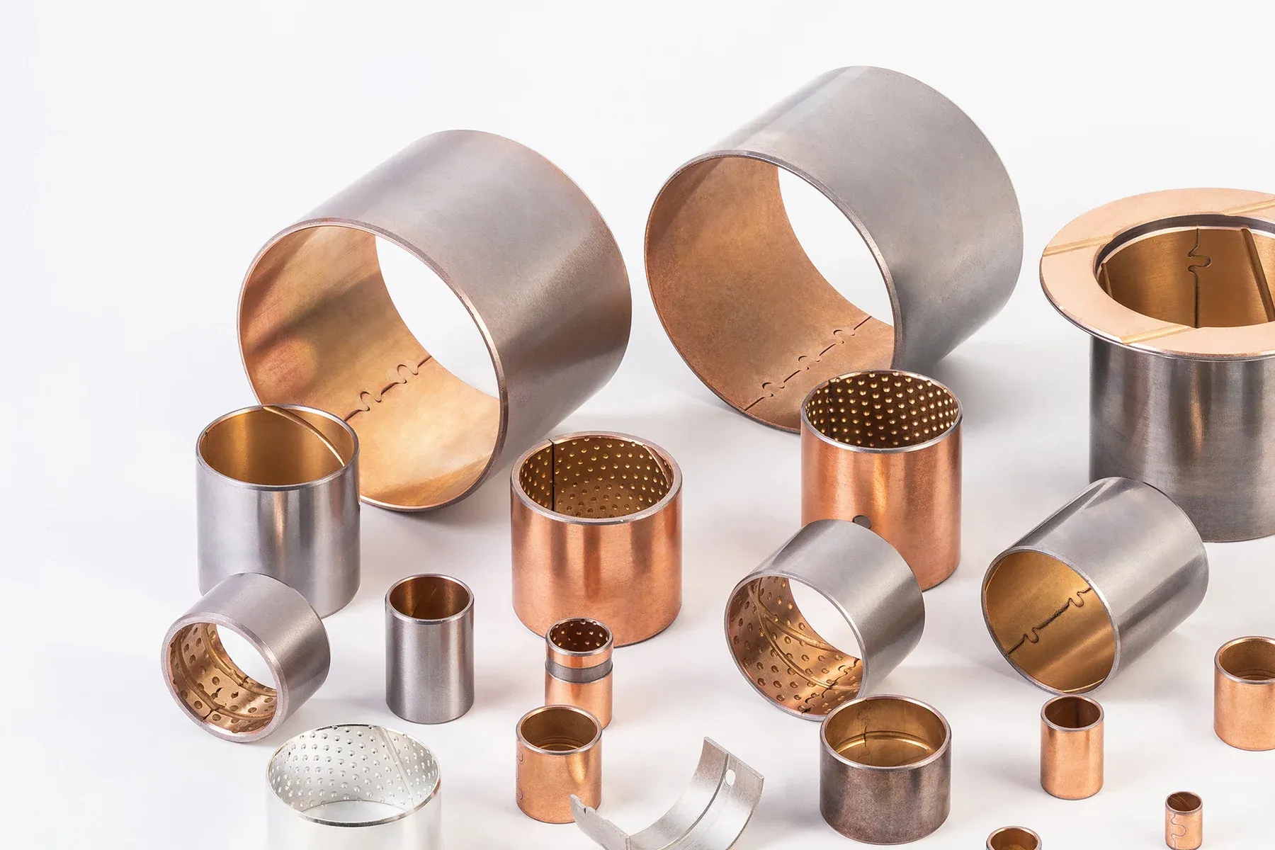
Bimetal bushing sizes
The standard metric series of JBM-800 wrapped bimetal bushings: 38 bores from Ø10 to Ø150 mm with 1.0, 1.5, 2.0 and 2.5 mm walls, lengths from 10 to 100 mm, an oil hole in every size, and the h8 shaft / H7 housing fits with the resulting installed bore and clearance. Flanged bushings, half bearings, thrust plates and other sizes are made to drawing.
A bimetal bushing is sized like any wrapped bushing: bore = nominal shaft, outside diameter = housing bore, wall in the 1–2.5 mm steps of the strip. Because the steel back is formed from strip, the bushing is a split sleeve that reaches its running bore only when pressed into the H7 housing; the installed bore and the h8 shaft together give the clearance in the table.
- Ø10–150 mm bore in 38 sizes; outside diameter = bore + 2, 3, 4 or 5 mm
- Lengths 10–100 mm; part code bore + length (4025 = Ø40 × 25 mm), length 0 / −0.40 mm
- Fits: shaft h8, housing H7; installed bore and clearance listed per size
- Oil hole Ø4–9.5 mm in every size; grooves and pockets to drawing
- Alloys: CuPb10Sn10 (JBM-800), CuPb24Sn4 (810), CuPb6Sn6Zn3 (820), CuSn10 (830), CuSn6.5P (840) on the same steel back
JBM-800 wrapped bimetal bushings (mm)
Standard series for an h8 shaft in an H7 housing. The installed bore applies after pressing into the H7 housing. Part code = bore + length: 4025 is Ø40 × 25 mm. Length tolerance 0 / −0.40 mm.
| Bore d | Outside Ø D | Shaft h8 | Housing H7 | Installed bore | Clearance | Wall S3 | Oil hole dL | Lengths L | Quote |
|---|---|---|---|---|---|---|---|---|---|
| Ø10 bimetal sleeve | 12 | 10 +0/−0.022 | 12 +0.018/0 | 10.010–10.148 | 0.010–0.170 | 0.935–0.995 | 4 | 10 · 15 · 20 | Quote |
| Ø12 bimetal sleeve | 14 | 12 +0/−0.027 | 14 +0.018/0 | 12.010–12.148 | 0.010–0.175 | 0.935–0.995 | 4 | 10 · 15 · 20 | Quote |
| Ø14 bimetal sleeve | 16 | 14 +0/−0.027 | 16 +0.018/0 | 14.010–14.148 | 0.010–0.175 | 0.935–0.995 | 4 | 10 · 15 · 20 | Quote |
| Ø15 bimetal sleeve | 17 | 15 +0/−0.027 | 17 +0.018/0 | 15.010–15.148 | 0.010–0.175 | 0.935–0.995 | 4 | 10 · 15 · 20 | Quote |
| Ø16 bimetal sleeve | 18 | 16 +0/−0.027 | 18 +0.018/0 | 16.010–16.148 | 0.010–0.175 | 0.935–0.995 | 4 | 10 · 15 · 20 | Quote |
| Ø18 bimetal sleeve | 20 | 18 +0/−0.027 | 20 +0.021/0 | 18.010–18.151 | 0.010–0.178 | 0.935–0.995 | 4 | 10 · 15 · 20 · 25 | Quote |
| Ø20 bimetal sleeve | 23 | 20 +0/−0.033 | 23 +0.021/0 | 20.020–20.161 | 0.020–0.194 | 1.430–1.490 | 4 | 10 · 15 · 20 · 25 | Quote |
| Ø22 bimetal sleeve | 25 | 22 +0/−0.033 | 25 +0.021/0 | 22.020–22.161 | 0.020–0.194 | 1.430–1.490 | 6 | 10 · 15 · 20 · 25 | Quote |
| Ø24 bimetal sleeve | 27 | 24 +0/−0.033 | 27 +0.021/0 | 24.020–24.161 | 0.020–0.194 | 1.430–1.490 | 6 | 10 · 15 · 20 · 25 · 30 | Quote |
| Ø25 bimetal sleeve | 28 | 25 +0/−0.033 | 28 +0.021/0 | 25.020–25.161 | 0.020–0.194 | 1.430–1.490 | 6 | 15 · 20 · 25 · 30 | Quote |
| Ø26 bimetal sleeve | 30 | 26 +0/−0.033 | 30 +0.021/0 | 26.040–26.181 | 0.040–0.214 | 1.920–1.980 | 6 | 15 · 20 · 25 · 30 | Quote |
| Ø28 bimetal sleeve | 32 | 28 +0/−0.033 | 32 +0.025/0 | 28.040–28.185 | 0.040–0.218 | 1.920–1.980 | 6 | 15 · 20 · 25 · 30 · 40 | Quote |
| Ø30 bimetal sleeve | 34 | 30 +0/−0.033 | 34 +0.025/0 | 30.040–30.185 | 0.040–0.218 | 1.920–1.980 | 6 | 15 · 20 · 25 · 30 · 40 | Quote |
| Ø32 bimetal sleeve | 36 | 32 +0/−0.039 | 36 +0.025/0 | 32.040–32.185 | 0.040–0.224 | 1.920–1.980 | 6 | 15 · 20 · 25 · 30 · 40 | Quote |
| Ø35 bimetal sleeve | 39 | 35 +0/−0.039 | 39 +0.025/0 | 35.040–35.185 | 0.040–0.224 | 1.920–1.980 | 6 | 20 · 25 · 30 · 40 · 50 | Quote |
| Ø38 bimetal sleeve | 42 | 38 +0/−0.039 | 42 +0.025/0 | 38.040–38.185 | 0.040–0.224 | 1.920–1.980 | 8 | 20 · 25 · 30 · 40 · 50 | Quote |
| Ø40 bimetal sleeve | 44 | 40 +0/−0.039 | 44 +0.025/0 | 40.040–40.185 | 0.040–0.224 | 1.920–1.980 | 8 | 20 · 25 · 30 · 40 · 50 | Quote |
| Ø45 bimetal sleeve | 50 | 45 +0/−0.039 | 50 +0.025/0 | 45.080–45.225 | 0.080–0.264 | 2.400–2.460 | 8 | 25 · 30 · 40 · 50 | Quote |
| Ø50 bimetal sleeve | 55 | 50 +0/−0.039 | 55 +0.030/0 | 50.080–50.230 | 0.080–0.269 | 2.400–2.460 | 8 | 30 · 40 · 50 · 60 | Quote |
| Ø55 bimetal sleeve | 60 | 55 +0/−0.046 | 60 +0.030/0 | 55.080–55.230 | 0.080–0.276 | 2.400–2.460 | 8 | 30 · 40 · 50 · 60 | Quote |
| Ø60 bimetal sleeve | 65 | 60 +0/−0.046 | 65 +0.030/0 | 60.080–60.230 | 0.080–0.276 | 2.400–2.460 | 8 | 30 · 40 · 50 · 60 | Quote |
| Ø65 bimetal sleeve | 70 | 65 +0/−0.046 | 70 +0.030/0 | 65.080–65.230 | 0.080–0.276 | 2.400–2.460 | 8 | 30 · 40 · 50 · 60 | Quote |
| Ø70 bimetal sleeve | 75 | 70 +0/−0.046 | 75 +0.030/0 | 70.080–70.230 | 0.080–0.276 | 2.400–2.460 | 8 | 30 · 40 · 50 · 60 · 80 | Quote |
| Ø75 bimetal sleeve | 80 | 75 +0/−0.046 | 80 +0.030/0 | 75.080–75.230 | 0.080–0.276 | 2.400–2.460 | 9.5 | 30 · 40 · 50 · 60 · 80 | Quote |
| Ø80 bimetal sleeve | 85 | 80 +0/−0.046 | 85 +0.035/0 | 80.080–80.235 | 0.080–0.281 | 2.400–2.460 | 9.5 | 30 · 40 · 50 · 60 · 80 · 90 | Quote |
| Ø85 bimetal sleeve | 90 | 85 +0/−0.054 | 90 +0.035/0 | 85.080–85.235 | 0.080–0.289 | 2.400–2.460 | 9.5 | 30 · 40 · 50 · 60 · 80 · 90 · 100 | Quote |
| Ø90 bimetal sleeve | 95 | 90 +0/−0.054 | 95 +0.035/0 | 90.080–90.235 | 0.080–0.289 | 2.400–2.460 | 9.5 | 40 · 50 · 60 · 80 · 90 · 100 | Quote |
| Ø95 bimetal sleeve | 100 | 95 +0/−0.054 | 100 +0.035/0 | 95.080–95.235 | 0.080–0.289 | 2.400–2.460 | 9.5 | 50 · 60 · 80 · 90 · 100 | Quote |
| Ø100 bimetal sleeve | 105 | 100 +0/−0.054 | 105 +0.035/0 | 100.080–100.235 | 0.080–0.289 | 2.400–2.460 | 9.5 | 50 · 60 · 80 · 90 · 100 | Quote |
| Ø105 bimetal sleeve | 110 | 105 +0/−0.054 | 110 +0.035/0 | 105.080–105.235 | 0.080–0.289 | 2.400–2.460 | 9.5 | 50 · 60 · 80 · 90 · 100 | Quote |
| Ø110 bimetal sleeve | 115 | 110 +0/−0.054 | 115 +0.035/0 | 110.080–110.235 | 0.080–0.289 | 2.400–2.460 | 9.5 | 50 · 60 · 80 · 90 · 100 | Quote |
| Ø115 bimetal sleeve | 120 | 115 +0/−0.054 | 120 +0.035/0 | 115.080–115.235 | 0.080–0.289 | 2.400–2.460 | 9.5 | 50 · 60 · 80 · 90 · 100 | Quote |
| Ø120 bimetal sleeve | 125 | 120 +0/−0.054 | 125 +0.040/0 | 120.080–120.240 | 0.080–0.289 | 2.400–2.460 | 9.5 | 50 · 60 · 80 · 90 · 100 | Quote |
| Ø125 bimetal sleeve | 130 | 125 +0/−0.063 | 130 +0.040/0 | 125.080–125.240 | 0.080–0.303 | 2.400–2.460 | 9.5 | 60 · 80 · 90 · 100 | Quote |
| Ø130 bimetal sleeve | 135 | 130 +0/−0.063 | 135 +0.040/0 | 130.080–130.240 | 0.080–0.303 | 2.400–2.460 | 9.5 | 60 · 80 · 90 · 100 | Quote |
| Ø135 bimetal sleeve | 140 | 135 +0/−0.063 | 140 +0.040/0 | 135.080–135.240 | 0.080–0.303 | 2.400–2.460 | 9.5 | 60 · 80 · 90 · 100 | Quote |
| Ø140 bimetal sleeve | 145 | 140 +0/−0.063 | 145 +0.040/0 | 140.080–140.240 | 0.080–0.303 | 2.400–2.460 | 9.5 | 60 · 80 · 90 · 100 | Quote |
| Ø150 bimetal sleeve | 155 | 150 +0/−0.063 | 155 +0.040/0 | 150.080–150.240 | 0.080–0.303 | 2.400–2.460 | 9.5 | 60 · 80 · 90 · 100 | Quote |
Type a bore in the filter box to find a row. The table defines the wrapped-bushing geometry; the bearing alloy (JBM-800 to JBM-840) is chosen separately and confirmed with the size at quotation.
Reading the table
d and D are the nominal bore and outside diameter; the shaft column gives the h8 shaft with its lower deviation and the housing column the H7 bore with its upper deviation. The installed bore is the range the bushing bore takes after it has been pressed into that housing; the clearance column combines the installed bore with the h8 shaft. S3 is the wall range and dL the catalogue oil-hole diameter; the position of the hole and any groove or pocket pattern belong on the part drawing.
The table is a standard-dimension reference, not a stock list, and it does not say that every alloy is available in every size: the alloy and size combination, the lubrication features and the quantity are confirmed together at quotation.
Fits and installed bore
Press fitting closes the wrapped shell against the housing, so the installed bore is read only with the H7 housing in the same row. A different shaft class changes the running clearance: an f7 shaft adds roughly 0.02–0.06 mm to the values listed. For oil-lubricated, higher-speed positions a larger clearance is often chosen; for slow, heavy, greased pivots the catalogue clearance is normal.
The sintered bronze lining is thin compared with a solid bronze wall, so the bore is not re-machined after fitting except by a light ream where the drawing allows for it. Align the housing bores of a shaft line-bored assembly before pressing rather than boring the bushings afterwards.
Alloys on the same sizes
The wrapped series is made with five sintered bearing layers on the same steel back: CuPb10Sn10 (JBM-800, the general-purpose leaded bronze), CuPb24Sn4 (JBM-810, high lead for poor lubrication), CuPb6Sn6Zn3 (JBM-820), and the lead-free CuSn10 (JBM-830) and CuSn6.5P (JBM-840). AlSn20Cu (JBM-850) is an oil-fed engine shell and journal material and does not follow the wrapped-bushing dimensions or greased-duty data in this table.
Measuring a bushing to order a replacement
Measure the steel-backed outside diameter and the full length at several positions, and record the finished housing bore and the shaft diameter with their tolerances if known; do not force the split closed to guess the installed bore. A flange, half bearing or formed part needs its own drawing. Measuring used parts is not a service we offer: we quote from your drawing or your measured dimensions, and against OE or competitor part numbers after comparing dimensions and material.
Frequently asked questions
What sizes do bimetal bushings come in?
The JBM-800 standard wrapped series covers Ø10–150 mm bore in 38 sizes with 1–2.5 mm walls and lengths of 10–100 mm. Flanged, half-bearing, thrust-plate and larger sizes are made to drawing.
Which shaft and housing tolerances do JBM-800 bushings use?
An h8 shaft and an H7 housing. The table lists the installed bore and the resulting diametral clearance for that pairing; another shaft class changes the clearance and is confirmed at quotation.
Is every alloy available in every size?
The table defines the geometry. Which alloy is made in which size, with which lubrication features, is confirmed at quotation; all five wrapped alloys share the same steel back and dimension series.
Can you make a bimetal bushing to a JF-800 or SAE 792 part number?
We quote against supplier part numbers, OE references and competitor designations after comparing dimensions and material. The designation alone does not establish interchangeability.
What does 4025 mean?
Bore 40 mm, length 25 mm: the catalogue part code is the bore followed by the length. The outside diameter follows from the table (44 mm for Ø40).
Quote a JBM-800 size from the table.
Use the “Quote” link on any row, or send bore × outside diameter × length with the alloy, oil-hole or groove pattern and quantity. Samples are free; there is no minimum order.