
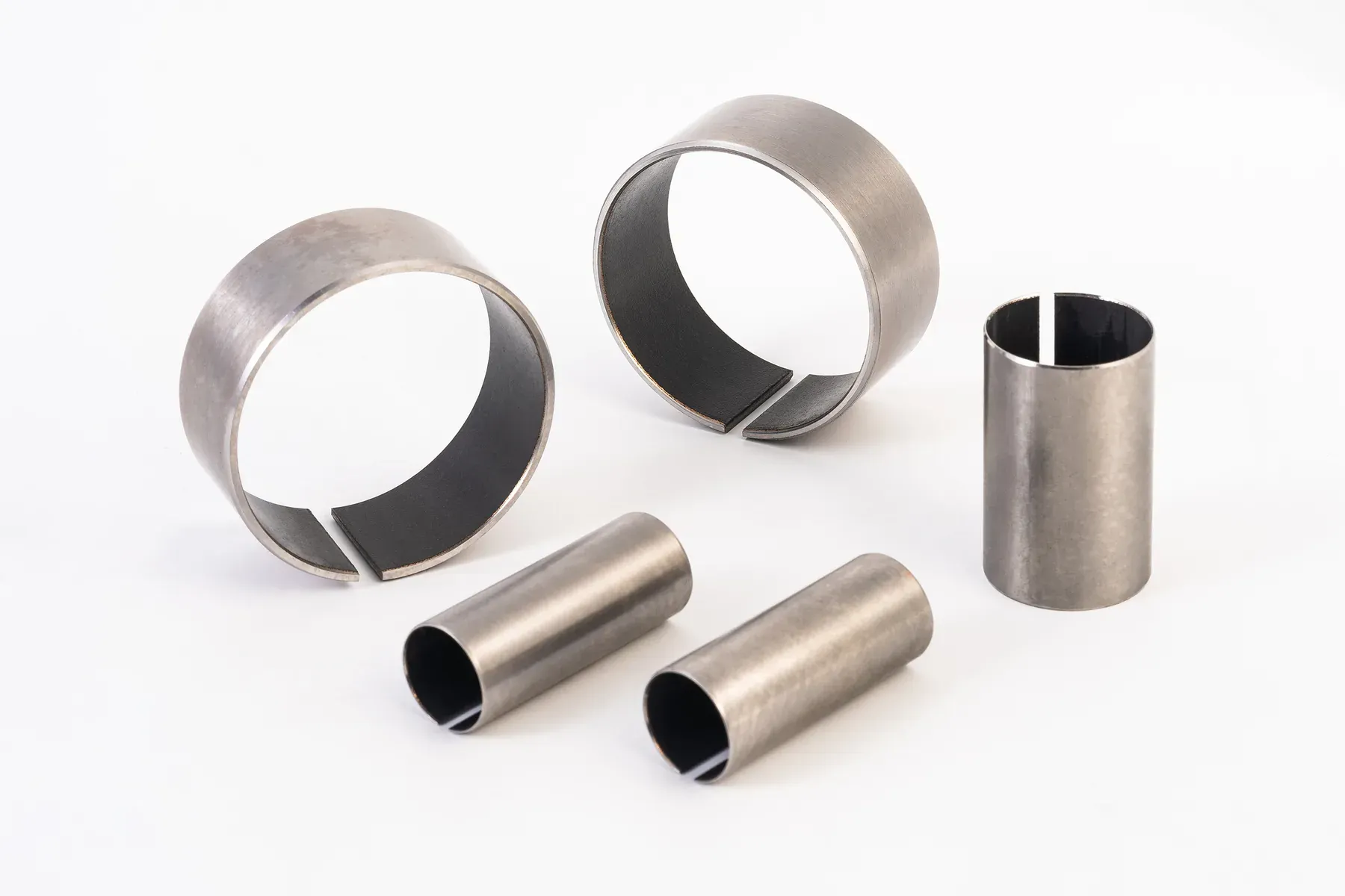
Hardened steel bushing sizes
JBM-ST hardened steel sleeves are made to order in metric and inch dimensions with a nominal metric bore range of 20–150 mm. Reference sizes are listed below; any other bore × outside diameter × length is quoted from your drawing.
Hardened steel bushing sizes are written as bore × outside diameter × length. The nominal size fixes the envelope; the fit against the pin and the housing, the groove pattern and the oil-hole position are set for the quoted part.
- Nominal metric bore range 20–150 mm; inch sizes on request
- Materials Grade 45, 40Cr, 20CrMo, GCr15; hardness HRC 58–62
- Reference sizes are made to order and confirmed at quotation; samples are free
- Sizes outside the range are machined to drawing
Metric reference sizes (mm)
Complete first-party references. Wall thickness is derived from bore and outside diameter.
Nominal range
| Parameter | JBM-ST |
|---|---|
| Metric bore range | 20–150 mm nominal inside diameter |
| Unit systems | Metric and inch |
| Steel grades | Grade 45 · 40Cr · 20CrMo · GCr15 |
| Bore hardness | HRC 58–62 |
| Bore features | Oil grooves and radial feed holes to pattern |
| Supply route | Made to order · free sample · no minimum order |
How a hardened steel bushing size is written
Three dimensions define the cylindrical envelope. Keep the symbols used on your drawing; the labels below explain the function of each measurement.
Bore d (inside diameter)
The running surface against the pin. Measure across the diameter; when wear, taper or ovality is visible on a used part, record the separate readings instead of an average.
Outside diameter D
The surface that locates in the housing. Exclude any flange and identify a stepped outside diameter separately.
Length L
Between the two end faces along the axis. A flange thickness, shoulder or counterbore needs its own dimension.
Show the part in end, side and section views
A single photograph or one diameter cannot define a steel bushing. The drawing must establish the envelope and locate every feature from a clear datum.
- End view: bore and outside diameter on common centrelines; flange diameter, bolt pattern or non-round profile where they exist.
- Side view: overall length, flange thickness, shoulders and steps; holes and grooves located from an end face.
- Section or detail view: groove shape, oil-hole diameter, chamfers, radii, undercuts and split orientation, with bearing, locating and clearance surfaces identified.
How to measure an existing steel bushing
A worn part removed from a machine is evidence of the assembly, not the nominal production drawing. Record the condition before measuring, and send us the readings: we quote from your dimensions or your drawing.
Label the sample condition
New, removed from service or still installed. Photograph both end faces and the side before cleaning.
Measure the bore at more than one position
Near both ends and at different angles with a bore gauge. Keep the readings separate when taper or ovality is present.
Measure the locating outside surface
On the cylindrical housing surface, away from damage, grooves or a split line. Record stepped diameters and flange diameter separately.
Capture length and axial locations
Overall length first; then flanges, shoulders, grooves and cross holes from the same end face.
Record construction details
Material markings, surface treatment, lubrication holes, groove pattern, chamfers and any split. Do not infer steel grade or hardness from colour.
Keep assembly dimensions separate
Record shaft and housing separately. The clearance or interference of a worn assembly is not a new-part tolerance.
Fit, tolerance and groove details
Nominal bore, outside diameter and length identify the envelope. Shaft clearance, housing retention, steel grade, hardness, surface finish and lubrication features complete the production definition.
- Set the fit from the pin and the housing: record pin diameter and housing bore separately; the running clearance and retention must suit your assembly, not another manufacturer’s table.
- Keep nominal size separate from tolerance: 55 × 65 × 45 states the envelope, not the permitted variation, finish, concentricity or heat-treatment route.
- Place oil holes and grooves by function: locate each from a defined end face and relative to the housing feed point and the loaded arc.
A CMM dimensional report for the finished part is issued on request.
Frequently asked questions
Which hardened steel bushing sizes are standard?
JBM-ST sleeves are made in standard metric and inch dimensions with a nominal metric bore range of 20–150 mm. The complete published references are 55 × 65 × 45 mm and 60 × 70 × 70 mm; every size is made to order and confirmed at quotation.
Do you make inch-size hardened steel bushings?
Yes. State the bore, outside diameter and length in decimal inches or fractions, with the unit, and we quote the inch part directly rather than converting a metric one.
What tolerances do you machine to?
To the fit stated on your drawing. If the drawing has none, send the pin diameter and the housing bore and we propose the running clearance and housing retention for the quoted part.
Can you copy a worn bushing?
We quote from a drawing or from dimensions you have measured; measuring a used part is not a service we offer. The measuring steps above show what to record so the quotation reflects the original nominal size rather than the wear.
Quote a reference size or send your own.
Bore × outside diameter × length, the pin and housing, the steel grade if you have one. Quotation within 12 hours, free sample, no minimum order.