
Bushing installation and press fit
A plain bushing is retained by interference alone, and the same interference closes its bore. This guide covers the housing, the fits for machined and wrapped bushings, how far the bore closes, how to press without damage, how to check the result and when to ream. It applies to bronze, bimetal, PTFE and POM composite, graphite bronze and steel bushings.
Machine the housing H7 with a chamfer, press the bushing in with a mandrel that supports the bore, and check the bore after pressing, not before: the interference that holds the bushing also shrinks it, by roughly the same amount for a thin wall and less for a thick one.
- Housing bore H7, round within the tolerance, chamfered 15–20° (composite) or 1–2 × 45° (bronze) at the mouth
- Machined bronze: OD s6 / r6 to ISO 4379, bore E6 before fitting, about H8 after
- Wrapped bushings: OD oversize per ISO 3547 / catalogue, bore reaches H9 (bronze) or the listed installed bore after pressing
- Press, never hammer; press on the end face with a stepped mandrel; align within 0.02 mm
- Ream after fitting only on solid bronze and steel; composite and bimetal are not re-machined
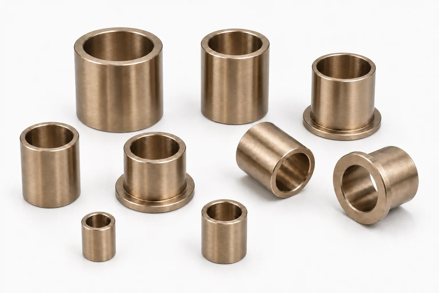
Prepare the housing
The housing does three jobs: it holds the bushing by friction, it sets the bushing geometry (a thin-wall bushing takes the shape of the bore it is pressed into) and it conducts heat away. Machine it H7 and check roundness as well as diameter; an oval or tapered bore gives an oval or tapered bushing. Break the mouth with a chamfer so that the bushing enters square: 15–20° over about 1 mm for wrapped composite and bimetal bushings, 1–2 mm × 45° for machined bronze. Remove burrs and clean the bore; a chip pressed under a thin steel back shows through as a high spot on the bore.
Housing material matters for thin-wall bushings. Aluminium and plastic housings expand more than the steel back of a composite bushing, so the grip falls as the assembly warms; use the upper end of the interference range, a longer bushing or a mechanical stop (flange, retaining ring or a pin through the housing).
Interference: how much and where it comes from
For machined bronze bushings ISO 4379 gives the fit system: the outside diameter is finished s6 up to Ø120 mm and r6 above, the housing is H7, and the interference that results is 18–59 µm at Ø48 and 43–101 µm at Ø115. The bore is finished E6 before fitting so that it closes to about H8 when pressed. The bronze size chart lists the deviations and the resulting interference and clearance for every size band, and the press-fit calculator gives them for any diameter.
For wrapped bushings the catalogue sets the interference rather than an ISO tolerance grade: a JBM-090 wrapped bronze bushing of Ø12 OD is made +0.065 / +0.030 mm oversize for a 12 H7 housing, and a JBM-10 PTFE bushing of Ø55 OD is +0.100 / +0.055. Wrapped bushings are split, so they press in with less force than a solid sleeve of the same interference and rely on the housing to close the split; the interference is deliberate and must not be reduced to ease assembly.
| Construction | Bushing OD | Housing | Bore before fitting | Bore after fitting | Shaft |
|---|---|---|---|---|---|
| Machined bronze, ISO 4379 | s6 (to Ø120) / r6 | H7 | E6 | ≈ H8 | e7–e8 |
| Wrapped bronze, ISO 3547 / DIN 1494 | Oversize per size table | H7 | Free (split, not measured) | H9 | f7–f8 |
| PTFE composite JBM-10 | Oversize per size table | H7 | Free (split) | Installed bore per table | f7 |
| Bimetal JBM-800 | Oversize per size table | H7 | Free (split) | Installed bore per table | h8 |
| Hardened steel, graphite bronze | Per drawing (typically s6–u6) | H7 | Per drawing | Per drawing | Hardened pin, per drawing |
How much the bore closes
A thin-wall bushing behaves like a ring: almost the whole radial interference at the outside reappears as a reduction of the bore. A wrapped bushing with 0.05 mm interference on the diameter closes about 0.05 mm on the bore, which is why the size tables list the installed bore rather than a free bore. A thick machined sleeve closes less because the wall carries part of the strain as compressive stress; for a wall equal to 10 % of the bore expect roughly 70–90 % of the interference to appear at the bore, and check it on the first-off part.
The consequence for the designer: the running clearance is set by the installed bore, not by the loose bushing, and the same bushing gives a smaller clearance in a housing at the low end of H7 than at the high end. The clearance columns on the size charts are the min–max of the whole tolerance stack. If your clearance window is narrower than that, specify the bore for machining after fitting (solid bronze) or a selected fit.
Pressing without damage
Press, never hammer: a hammer cocks the bushing, folds the leading edge of a thin wall and mushrooms the end face of a bronze sleeve. Use an arbor press or a hydraulic press with a stepped mandrel whose pilot fits the bore with 0.1–0.2 mm clearance and whose shoulder bears on the end face; the pilot keeps the bushing square and supports a split bushing so the split edges cannot fold inward. For flanged bushings press on the flange face with a flat plate over the mandrel, not on the flange rim. Position the split of a wrapped bushing away from the load zone, ideally at 90° to it, and any oil hole or groove in line with the housing feed.
Align the bushing within 0.02 mm across its length before applying force; a bushing that starts crooked shaves the housing and enters oversize. Large bronze bushings can be shrunk with dry ice or liquid nitrogen instead of pressed, which avoids scoring the housing; heating the housing works for steel and cast-iron housings but not for a composite bushing, whose PTFE layer must not exceed its temperature limit. A light film of oil on the housing bore eases pressing for bronze and steel; keep it off the bore of a composite bushing, which must run dry unless the design says otherwise.
| Step | Machined bronze / steel | Wrapped bronze, bimetal, composite |
|---|---|---|
| Check housing | H7, chamfer 1–2 × 45°, clean | H7, chamfer 15–20°, clean, no burrs |
| Tool | Stepped mandrel or shrink fit | Stepped mandrel with pilot supporting the bore |
| Orientation | Oil hole to feed; grooves clear of load zone | Split at 90° to load; hole to feed |
| Force | Steady press; watch for scoring | Steady press; less force, stops when flush |
| After fitting | Check bore; ream if drawing says so | Check installed bore in situ; never ream |
Checking the installed bore
Measure the bore after pressing, in the housing, at two positions along the length and two angles: a bore gauge or a plug gauge, not a caliper. Compare with the installed bore in the size table or the drawing. A tight spot at one end means the housing was not round or the bushing entered crooked; a bore larger than the table means the housing is oversize and the bushing is not fully gripped. For wrapped bushings ISO 3547-2 describes checking the outside diameter in a ring gauge and the bore in a test housing; a free-state caliper reading is not an acceptance measurement.
Then check the shaft: hardness and finish per the material (see the selection guide), and clearance against the installed bore. Rotate the shaft by hand; it should turn freely with no tight spot before the machine is loaded.
Reaming and line boring after fitting
Solid bronze and steel bushings can be finished after pressing, and for a line of bushings on one shaft they should be: press all bushings, then ream or line-bore them together so that they are coaxial regardless of the housing tolerances. Order the bore with machining stock (typically 0.1–0.3 mm) if this is the plan. Graphite-plugged bronze can be lightly reamed; keep the cut shallow so the plugs are not smeared.
Composite and bimetal bushings are not re-machined: the PTFE or POM layer is thin and the sintered bronze lining is only a fraction of a millimetre. If the clearance after fitting is wrong, the housing or the shaft must change, not the bushing. Wrapped bronze bushings may be lightly sized only where the drawing allows for it, because cutting through the pockets or holes removes their lubricant capacity.
Lubrication at assembly
Cast bronze and bimetal: fill the grooves or pockets and coat the shaft with the service grease or oil before the first start. Wrapped bronze JBM-090: fill the diamond pockets with grease; JBM-092: connect the through holes to the housing feed and prime it. POM composite JBM-20: apply a compatible grease across the whole running surface so the pockets are filled; it is not a dry-running bushing. PTFE composite JBM-10, graphite bronze and sintered bronze: assemble dry and clean; oil on a PTFE liner is harmless but unnecessary, and grease in a dusty environment turns into an abrasive paste.
Put the fit on the drawing: housing H7, bushing OD class or catalogue oversize, bore before and after fitting, shaft class, and whether the bore is to be machined after fitting. We quote against the fit stated on the drawing.
Installation faults and what they look like
A bushing that walks out of the housing in service had too little interference or a housing that expands more than the bushing: check the housing bore and material, and add a flange or retaining feature. A tight bore after fitting on a thin-wall bushing means the housing was at the low end of H7 or undersize; the fix is the housing, not a reamer. Bell-mouthed or folded edges come from a missing chamfer or a mandrel without a pilot. Scoring on the outside diameter means the bushing entered crooked or the housing had a burr. A wrapped bushing with the split in the load zone shows a wear line at the split and early failure; re-orient it. Early wear on a POM composite bushing is almost always an unfilled pocket surface at assembly.
Frequently asked questions
What tolerance should the housing bore be for a bushing?
H7 for every type. The bushing outside diameter carries the interference: s6 / r6 for machined bronze to ISO 4379, a catalogue oversize for wrapped bronze, bimetal and composite bushings.
How much interference does a bronze bushing need?
ISO 4379 pairs an s6 outside diameter with an H7 housing, giving about 18–59 µm at Ø48 and 43–101 µm at Ø115. The bronze size chart and the press-fit calculator give the values for any size.
Does the bore shrink when a bushing is pressed in?
Yes. A thin-wall bushing closes by nearly the full interference; a thick machined sleeve by 70–90 % of it. That is why the bore is finished E6 before fitting and reaches about H8 after, and why wrapped bushings are specified by installed bore.
Can I ream a bushing after pressing it in?
Solid bronze and steel bushings, yes, and for a line of bushings you should. Composite (PTFE, POM) and bimetal bushings, no: the running layer is too thin. Wrapped bronze only where the drawing allows a light sizing.
Should I grease a PTFE bushing at installation?
No. JBM-10 PTFE composite runs dry; assemble it clean. Grease is needed for POM composite (JBM-20), wrapped bronze pockets, bimetal and cast bronze.
Where should the split of a wrapped bushing go?
Away from the load zone, ideally at 90° to the direction of the load, with any oil hole aligned to the housing feed.
Send the drawing with the fit and we quote against it.
Housing, bushing and shaft tolerances, whether the bore is machined after fitting, quantity. Samples are free; the first-off installed bore can be checked on request with a CMM report.